 ASTM E9 defines testing techniques for compression testing of metals. Using these techniques the parameters of compressive yield strength, compressive ultimate strength, and compressive modulus can all be determined on a variety of geometries of metallic materials.
The compressive strength of metallic materials including steel and aluminum can be important in the design of structures such as buildings and bridges, as well as many other product designs. Metallic materials are extremely stiff in compression. Therefore accurate compression tests of metals can be challenging.
Preparing the Sample
As defined in table 1 of the standard, you should use a cylindrical geometry specimen if you have the opportunity to choose the geometry of your test specimen. These cylindrical geometries are chosen to minimize the potential for undesirable buckling.
Table 2 of the standard defines a range of sizes that the specimens should be. The diameter of the specimen should be between 12.7 mm (0.5 in) to 31.75 mm (1.25 in). Heights range from 25.4 mm (1 in) to more than 152.4 mm (6 in).
If you must test rectangular or sheet specimens, TestResources can assist you with special fixturing which will carefully maintain the vertical alignment and loading on your specimen to avoid buckling. Contact your TestResources application engineer and be ready to discuss the details of the geometry of your specimen.
In some cases, if the specimen is extremely stiff, a high resolution deflectometer should be used to ensure very accurate compressive deflection measurement. For tall thin specimens, there is a risk of column buckling. The horizontal bulging of the diameter of the specimen, also known as barrelling, can also be a concern. To minimize this risk use an upper spherical bearing platen, and center the specimen very carefully on the platens. If buckling or barrelling is evident you should change to a shorter specimen.
Test Procedure
Compression tests of metals can be performed on a TestResources electromechanical universal test machine or servo-hydraulic test machine. Depending on the type of material being tested and the size of the specimen, the max force can vary. We offer several test machines that offer a wide force range. Large forces may be necessary so do some research to ensure that your test machine has sufficient force capacity. Your TestResources application engineer can help.
After you have prepared the test sample, you should measure the specimen's width and thickness (diameter) and calculate the average of the cross-sectional area on the specimen’s gauge section.
The G223 spherical bearing compression platen should be placed on the machine so that it is directly above the specimen. This platen will ensure uniform compressive loading on the specimen by virtue of the platens’ spherical bearing. The G23 fixed compression platen should be placed so that it is beneath the specimen. Once your platens are secured to the test machine you should place the test specimen carefully in the center of the fixtures. Attach a deflectometer to the gauge section of the sample, if required.
Set the load range of the test machine so that the maximum expected load is approximately 1/3 of the load range. The elastic load vs. strain should be between 30˚ and 60˚ to the load axis. Apply the load at a constant speed rate of 0.005 in/min.
If you will be testing ductile samples then the test will be over once the compressive force and compressive deflection has been determined. If you will be testing brittle samples then the test will end when the sample breaks. Caution: If you will be testing thin metals that are at all brittle, then there may be risk of sudden specimen failure with fracturing of the specimen material. That may be unsafe to the test operator. Discuss your testing plans with your TestResources application engineer. We can provide safety cages on all of the test machines we build.
Once the test has been run and you have collected compressive force and compressive deflection data then you should begin calculating the compressive strength, compressive modulus and the compressive stress-strain curve. It is recommended that you use the offset method to calculate the compressive yield strength. The 0.2% offset method is the most common. This offset should be stated along with the calculation.
Recommended Test Machines

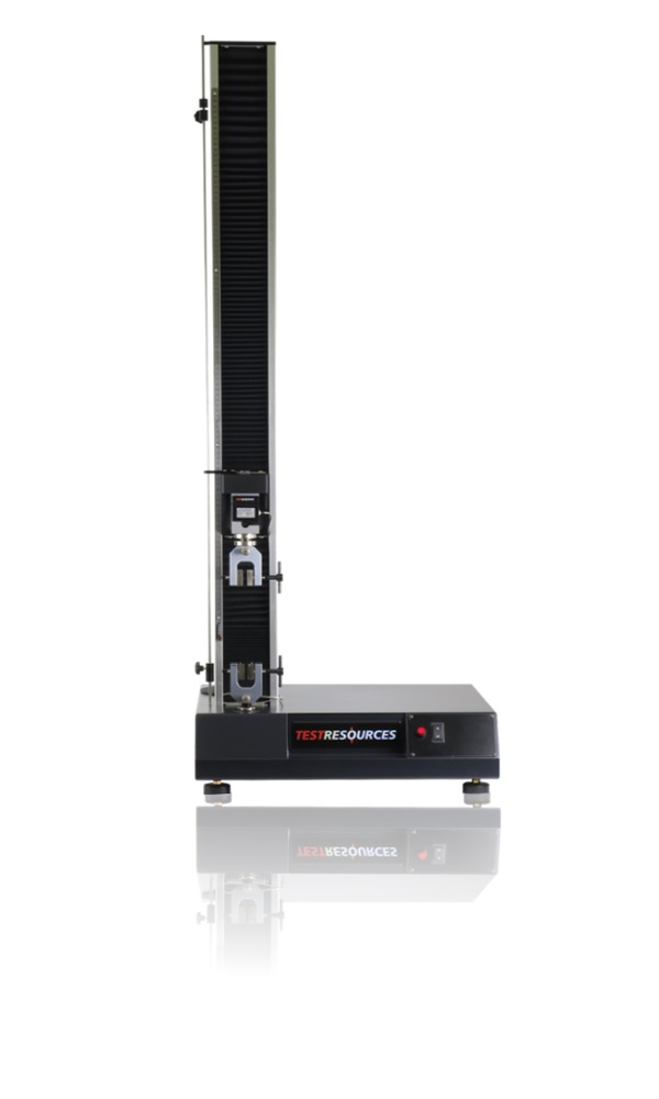
Forces up to 10 kN (2,250 lbf)
Low force tabletop systems
Modular series of five frame options with adjustable test space
Affordable testing option for tension, compression, bend, peel and much more
Forces up to 5 kN (1,125 lbf)
Low force tabletop systems
Tests at speeds up to 2,500 mm/min (100 in/min)
Best for high travel or high elongation test requirements
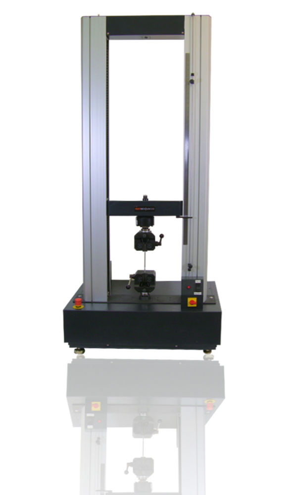
Force range of 5 kN to 600 kN (1,125 lbf to 135,000 lbf)
Adjustable test space
The most popular choice for static tension and compression tests
These dual column testers are available in both tabletop and floor standing models
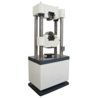
Force range of 300 kN to 2,000 kN (67,500 lbf to 450,000 lbf)
The best choice for performing static tension and/or compression applications when force capacities of 300 kN (67,000 lbf) or more are needed
Includes its own grips
Recommended Testing Accessories
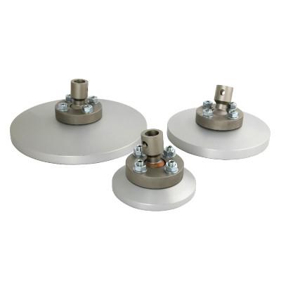
Standard load ratings up to 300 kN (67,500 lbf) *higher ratings available upon request
Platen diameters available from 56 mm to 196 mm (2.2 in to 7.7 in)
Articulating platen aligns itself to specimen geometry
Available in steel or aluminum construction
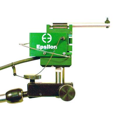
Available from a 1 mm (0.04 in) measurement range to a 25 mm (1.0 in) measurement range
May be used in a wide variety of tests
Includes a magnetic and adjustable mounting base
Standard units meet Class B-1 of ASTM E83, Class 0,5 of ISO 9513