JEDEC 9702 monotonic bend testing method is intended to characterize the fracture strength of a components board-level interconnects. It is applicable to surface mount components attached to printed wiring boards using conventional solder reflow technologies. The monotonic bend characterization results provide a measure of fracture resistance to flexural loading that may occur during conventional non-cyclic board assembly and test operations, and supplements existing standards that address mechanical shock or impact during shipping, handling or field operation.
Equipment required
The crosshead travel distance and crosshead speed of a 100 or 200 series TestResources test machine needs to be configured to be approximately proportional to the test board assembly strain and strain-rate, respectively. The relationship between these variables can be determined empirically by testing a mechanically representative package/board assembly (set-up test board); however, these relationships may prove non-constant or non determinant, depending on the configuration and board/ package configuration.
This test method specifies use of the simplified analytical relationships to establish the test machine control settings for crosshead travel distance and crosshead speed, based upon global PWB strain and strain-rate input variables, respectively. These equations are derived from classic beam theory and ignore any effects due to the package(s), or to the Poissons ratio effect of a plate in bending.
Note from 8.12 - Four-Point Bend Test should be oriented such that the component leads or solder joints are placed in tension during the four point bend test. Empirical testing indicates that board-level package solder connections are typically more susceptible to fracture with increased strain-rate (at comparable PWB strain levels). Testing conducted at crosshead speeds less than specified will tend to overstate fracture strength of a components board-level interconnects; hence, test equipment and test board configurations should be selected that meet the minimum crosshead speed shown below, wherever possible, to insure consistent, conservative reporting of interconnect strength.
By means of our bend testing expertise and modular product design, we will help find the testing solution that is right for you. Give one of our application engineers a call today for help with creating the best budget and testing plan according to JEDEC 9
Recommended Test Machine
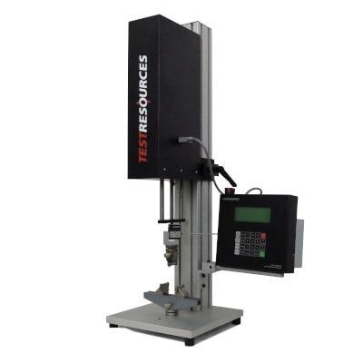
Forces up to 10 kN (2,250 lbf)
Low force tabletop systems
Modular series of five frame options with adjustable test space
Affordable testing option for tension, compression, bend, peel and much more
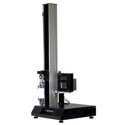
Forces up to 5 kN (1,125 lbf)
Low force tabletop systems
Tests at speeds up to 2,500 mm/min (100 in/min)
Best for high travel or high elongation test requirements
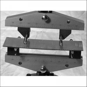
Recommended Testing Accessories
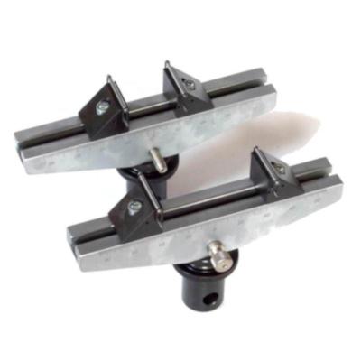
Load ratings up to 10 kN (2,250 lbf)
Interchangeable roller diameters from 1 mm to 12.7 mm (0.04 in to 0.5 in)
Easily adjustable span
Base lengths of 150 mm (6 in) and 300 mm (12 in)