Printed circuit board assemblies experience various mechanical loading conditions during assembly and use. The repeated flexing and cyclic bending of board can cause electrical failures due to circuit board and trace cracks, solder interconnects cracks, and component cracks. Although the number of repeated bend cycles may be small, the magnitude of flexure can be very significant. The actual use conditions such as repeated key-presses in mobile phone can result in a large number of repeated bend cycles during the life of the product, at a lower magnitude. This board level test method is needed to evaluate the performance of mounted components due to repeated bending of board and compare their performance with other components.
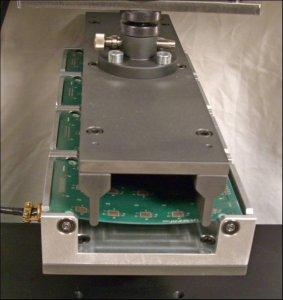
The standard covers 4-point bend method for cyclic bend performance characterization of components. The printed wiring board assembly rests on two support anvils while deflecting the board in the downward direction by displacing the load anvils. The test results in constant curvature of the board in between the two inner anvils if there are no components on the board. With components mounted, the local strain in the component region will be different from the global PWB strain. Due to large number of cycles for this test, the board may move on the anvils in the plane of the board (right / left). The movement is controlled to 1 mm max in each direction from the absolute center position of the roller anvil by designing some constraining features in the test fixture.
Equipment Required
By means of our testing expertise and modular product design, we will help find the solution that is right for you. Give our test engineers a call today for help configuring the best test machine and accessories according to your standard.
Recommended Test Machine
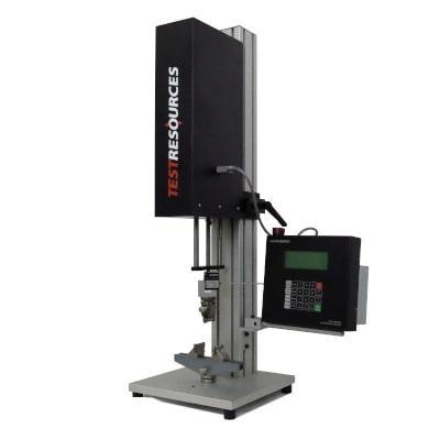
Forces up to 10 kN (2,250 lbf)
Low force tabletop systems
Modular series of five frame options with adjustable test space
Affordable testing option for tension, compression, bend, peel and much more
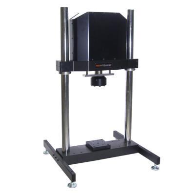
Static and fatigue forces up to 50 kN (11,250 lbf)
Frequency ratings up to 75 Hz
Oil-free, all electric actuator for clean test conditions
Lower purchase, operating, and maintenance costs than hydraulic equivalents